| Precautionary Measures | Recommended Tools | ||
| Procedures for Customer-Replaceable Parts | Screw Identification and Tightening | ||
| Procedures for Field- and Depot-Replaceable Parts | ZIF Connectors |
| Back to Contents Page | Glossary |
| Precautionary Measures | Recommended Tools | ||
| Procedures for Customer-Replaceable Parts | Screw Identification and Tightening | ||
| Procedures for Field- and Depot-Replaceable Parts | ZIF Connectors |
| CAUTION FOR YOUR PERSONAL SAFETY AND
PROTECTION OF THE EQUIPMENT
Before you start to work on the computer, perform the following steps in the sequence indicated:
|
You must also take the following steps:
The preceding steps are described in detail in Procedures for Customer-Replaceable Parts.
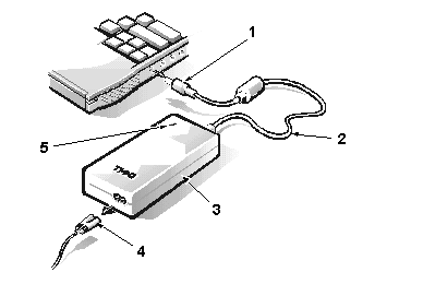
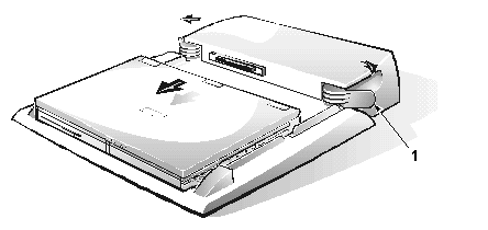
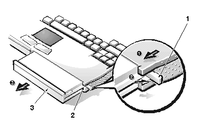
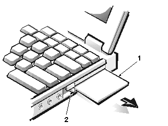
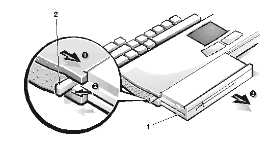
To disconnect the computer from the AC adapter and port replicator, and to remove the main battery, PC Cards, hard-disk drive, RAM door, memory modules, and device in the media bay, perform the following steps.
| NOTE: The following procedures can be performed by customers as well as Dell-certified repair technicians. |
 |
|
 |
|
| CAUTION: The battery is designed to work with Dell Inspiron 3500 computers only. Do not use a battery from another computer with the Dell Inspiron 3500 computer. Replace the battery only with the same or equivalent type purchased from Dell. Using the wrong battery type may present a risk of fire or explosion. | |
| CAUTION: The battery may present a fire or chemical burn hazard if mistreated. Do not disassemble, expose the battery to temperatures above 60ºC (140ºF), or incinerate. Keep the battery away from children. Handle damaged or leaking batteries with extreme care. If the battery is damaged, electrolytes may leak from the cells and cause personal injury. Dispose of a used battery promptly. |
Pull the battery-bay release latch (located on the side of the computer
next to the battery bay) toward you. With your thumb, gently rotate the latch
out until the battery pops out of the bay. Grasp the battery firmly and
remove.
 |
|
 |
|
| Type of Screw | Torque |
| FPH 3 x 4 (1) | 2.0–2.5 kgf-cm |
NOTICE: Hard-disk drives are extremely fragile and must be handled carefully. Even a slight jar or bump can damage the spinning heads and plates, thus rendering the drive inoperable.
NOTICE: Hard-disk drives are extremely fragile and must be handled carefully. Even a slight jar or bump can damage the spinning heads and plates, thus rendering the drive inoperable.
| CAUTION: The hard-disk drive may be hot to the touch. Do not touch the plastic carrier of the hard-disk drive if you remove the drive from the computer when the drive is hot. |
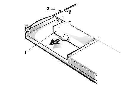
Turn the computer over and remove the 4-mm screw securing the hard-disk
drive to the bottom of the computer. The screw has an H tooled into
the plastic beside it. Grasp the plastic tab and pull the hard-disk drive
forward and out.
 |
|
| Type of Screw | Torque |
| FPH 3 x 4 (2) | 2.0–2.5 kgf-cm |
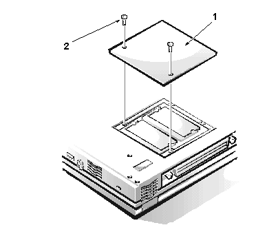
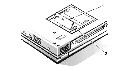
Remove the two 4-mm screws from the memory door (also known as the memory
module cover). Using your finger, lift the door off.
 |
|
 |
|
 |
|
NOTES: If the computer is booted with a diskette drive or second battery in the media bay, you must reboot after installing another device in the media bay. To remove the media from the CD-ROM drive, DVD-ROM drive, or Zip drive once the power to the drive is off, insert a small, thin object (such as one end of a paper clip) into the pinhole near or in the device’s LED. This ejects the media or the media tray so you can retrieve the CD, DVD, or Zip disk.
| CAUTION: Only a certified service technician should perform these procedures for removal, replacement, and installation of parts. The warranty on the computer becomes void if anyone other than a certified technician performs these procedures. |
NOTICE: During the removal and replacement procedures, you will see Kapton tape in many places on the computer. When reinstalling or replacing parts, be sure to replace the Kapton tape correctly to retain the electrical protection and noise reduction the tape provides.
Unless otherwise noted, each procedure assumes the following:
Procedures for field- and depot-replaceable parts are described in these sections:
Most of the procedures require the use of one or more of the following tools:
NOTICE: The correct-length screw must be used when reinstalling a screw. Otherwise, hardware damage could result. Make sure that the screw is properly aligned with its corresponding hole, and avoid overtightening.
Where applicable, information about screw lengths is provided with the illustrations.
The Inspiron 3500 portable computer contains many screws of various sizes. Be careful not to scratch the computer plastic case by allowing screws to get between the disassembly surface and the plastic case. Dell suggests a soft, padded work surface.
While removing and replacing parts, use a tackle or pill box as a storage device to keep track of the screws. Use the following location template to store the screws during disassembly.
| NOTE: Each removal and replacement procedure lists the type, size, and torque value of screws removed during the procedure. Screw types include flat head (FLH), flat pan-head (FPH), pan head (PNH), and jack screws. |
| Hard-disk drive: | RAM
door:
3 x 4 (2) |
Display
assembly:
2.5 x 19 (4) |
| Bezel:
2.5 x 5 (6) |
LCD
interior assembly:
2.5 x 5 (2) |
LCD
panel rails (13.3"):
2.5 x 5 (4) |
| LCD
panel rails (14.1"):
2 x 4 (4) |
Diskette
drive:
2.5 x 4 (2) |
CD-ROM/DVD-ROM
drive:
2 x 3 (3) |
| Iomega
Zip drive:
2.5 x 5 (2) |
Keyboard:
2.5 x 16 (3) |
Infrared
board:
2.5 x 5 (1) |
| Heat-sink
fin cover:
2 x 3.5 (1) |
Processor
module assembly:
2 x 14 (2) |
Fan
cover:
2.5 x 5 (1) |
| Modem
card:
2.5 x 14 (1) |
Video
board:
2.5 x 4 (2) |
Palmrest:
2.5 x 19 (7) |
| Touch
pad assembly:
2.5 x 5 (3) |
System
board rails:
2.5 x 5 (2) |
DC/DC
board:
2.5 x 14 (1) |
| PC
Card cage:
2 x 14 (4) |
System
board:
2.5 x 5 (1) |
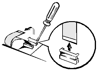
NOTICE: ZIF connectors are fragile. To avoid breaking the connectors, touch them carefully. Do not apply too much pressure to the movable part of the connector when opening or closing it.
Some of the computer’s interface connectors are ZIF connectors. These connectors are not removable; they must be released to disconnect a cable from them.
To disconnect a cable from a ZIF connector, perform the following steps:
To reconnect an interface cable to a ZIF connector, perform the following steps:
| Back to Contents Page | Glossary |